Development, from mine pump to Haarlemmermeer engine.
The precursors of the Haarlemmermeer engines.
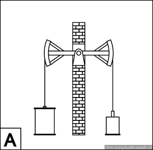
The Cornish pumping engine is the direct descendant, of the Newcomen engine, via the earliest engines of James Watt. All are non-rotative engines, i.e., the straight-line motion of a power piston is transmitted to the straight-line motion of a pump piston, without a crank or flywheel. Often the power and pump cylinders are vertical, and power is transmitted from one to the other via a horizontal lever, the beam.
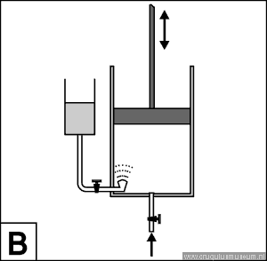
The Newcomen engine dates from about 1715. The piston was pulled up by the weight of the pump piston and steam of virtually atmospheric pressure (barely more than the pressure in a kettle) entered the cylinder. The steam was then condensed by injecting water directly into the cylinder. This created a vacuum, which pulled the piston down in the open-top cylinder (or, rather, the pressure of the atmosphere pushed it down). The repeated cooling and heating of the cylinder made this engine extremely wasteful of fuel. The overall efficiency was not more than 1/2 per cent.
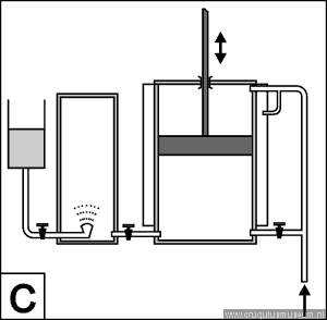
In 1769 James Watt added a separate vessel for condensing the steam. This condenser could remain cold, while the cylinder remained hot. A valve between the cylinder and the condenser was opened during the part of the stroke when a vacuum was needed. To conserve heat, Watt closed the top of the cylinder and let steam push the piston down. This steam was still low pressure. Watt also enclosed the cylinder in a steam jacket to keep it hot. Efficiency increased dramatically, to over 2 per cent.
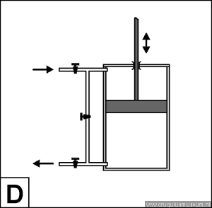
After Watt’s patent expired, Cornish engineers introduced higher steam pressures. This and the addition of a steam valve allowed expansive working. Cornish engines with extremely high expansion could reach efficiencies of up to 11 per cent.
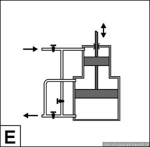
The very brief period during which steam was admitted produced the effect of a violent `kick´ on the piston (and all connected parts). James Sims designed an engine which ran much more smoothly and still had a comparable efficiency. This he achieved by cascading two cylinders of unequal diameter. Boiler steam was admitted to the smaller cylinder and expanded here to some extent. The steam then was led from the small cylinder to the larger one using a bypass pipe and further expanded there. Each of the expansion stages caused less of a kick. An engine with two-stage expansion is called a compound engine. The space between the two pistons was kept at a constant pressure. Any pressure would do in principle, but connecting this space to the atmosphere would increase the risk of air leaking in via the packing of the large piston, spoiling the condenser vacuum. This was avoided by permanently connecting the space between the pistons to the condenser.
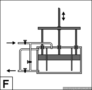
The Sims compound engine performed reasonably well, but it was very tall. For the great engines proposed for the Haarlemmermeer drainage stations, the sheer height of the engines was expected to make them unstable. The designers therefore eventually decided to telescope the small cylinder into the large one, which then became annular. The space between the pistons in the regular Sims engine was reduced to just a small space above the annular piston.
For bucket pump operation, the weight surplus would have to be placed at the engine ends of the beams, i.e., inside the building. This is just the opposite of regular Cornish engine practice. In consequence, the engine had to be turned upside down. The illustrations of the steam cycle show what the engine would look like in that case
Drawings Robert J H Gisolf