Introduction
Since June 2002 Cruquius moves again, after more than 20 years of hard work, the combined efforts of volunteers, experts and of course the sponsors.
On the restoration page you can read that research and activities to make the large Cruquius engine move again started in 1982. Using steam drive was out of the question because Cruquius’ set of boilers was removed in 1935 and installing a new steam supply would be both expensive and difficult from practical and technical points of view. So various other ways of driving the engine were studied and eventually modern hydraulic techniques were chosen.
The mineral oil hydraulics solution
1. The hydraulic cylinders
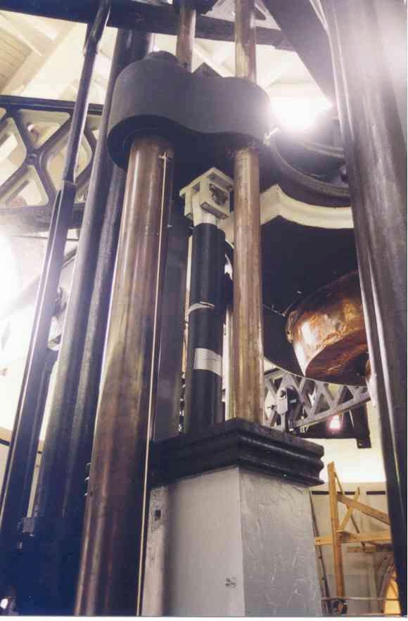
Two hydraulic cylinders, one at each end of the engine, are going to move the Cruquius engine. Many different ways to connect the hydraulic cylinders to the old engine were compared. The placing of the cylinders would have to be as invisible as possible for they were no part of the original engine. But at the same time they would have to be placed in such a way that they could resist the tremendous forces. Finding a suitable place was not easy at all. Until one day Steam Team member Aat Cappellen van Walsum got a brilliant idea, while he was looking around in the engine room. He suggested to ‘simply’ place them between the guide rods. That turned out to be the perfect spot, so it is now indeed the location where the two hydraulic cylinders were mounted.
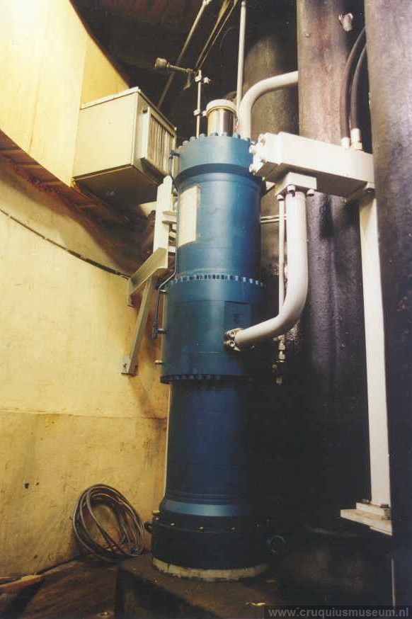
2. The construction of the cylinder
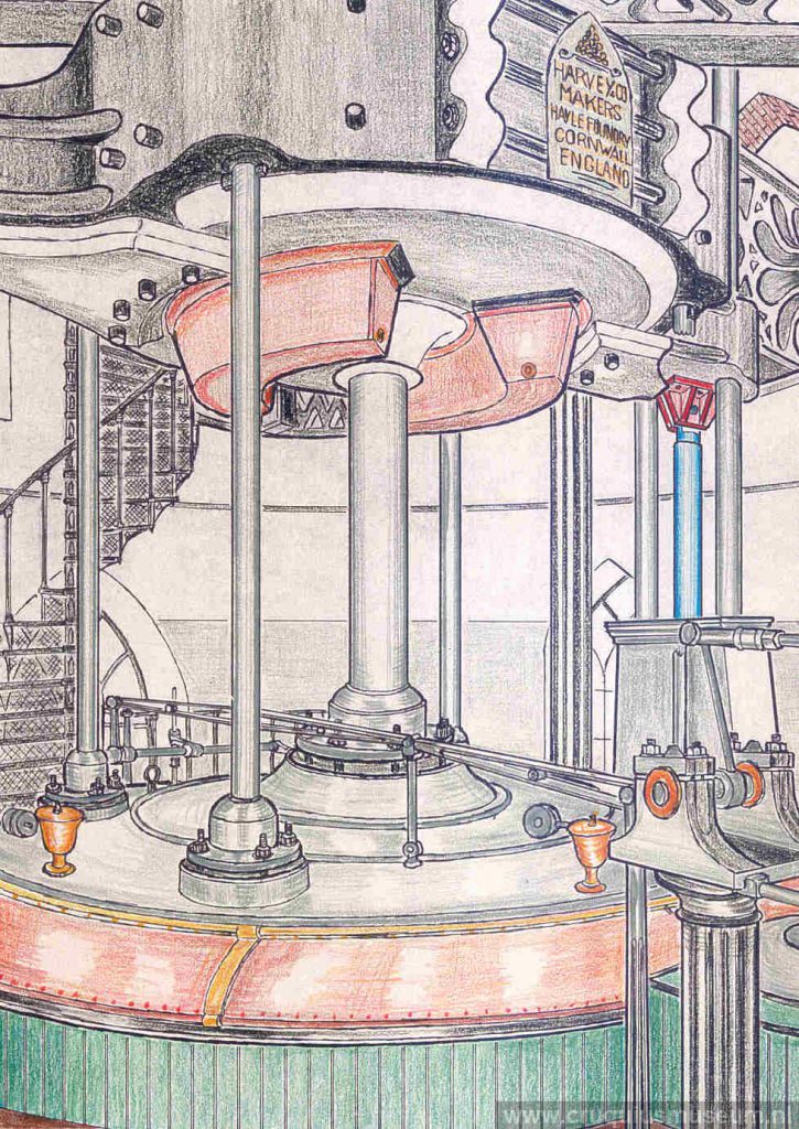
The (blue) hydraulic cylinder.
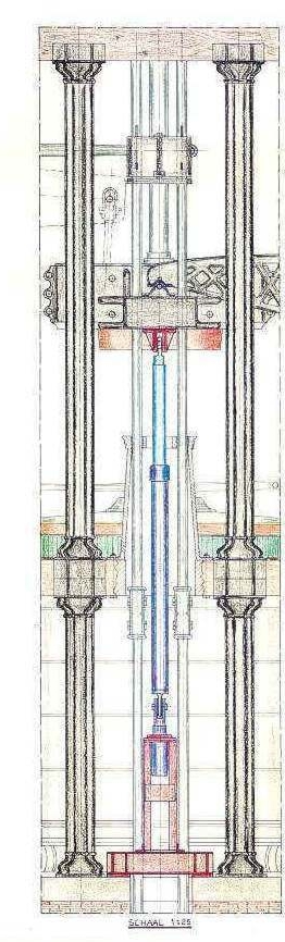
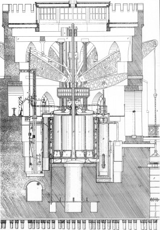
Left and right, massive cast iron columns rise from the brick and stone engine foundation block to support the main floor beams and the roof beams. The weight cap is guided by two wrought iron rods fitted with top and bottom stops or buffers. The bottom buffer is a cast iron box filled with woodblocks, sitting on a main floor beam. The guide rods continue downwards into the foundation as tension rods. This entire support and guide structure is duplicated on the other side of the steam cylinder. The new (blue) hydraulic cylinders (to push the weight up) pass through the bottom buffer boxes, to s support structure (red) which stands on the foundation block. The hydraulic pistons must of course move synchronously. This is achieved by feeding the oil via a special synchronizing cylinder.
The hydraulic drive
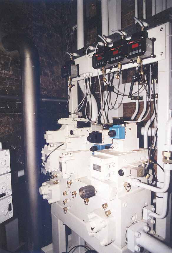
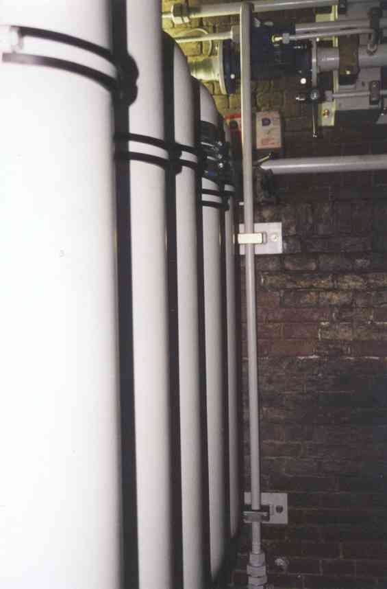
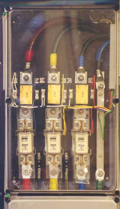
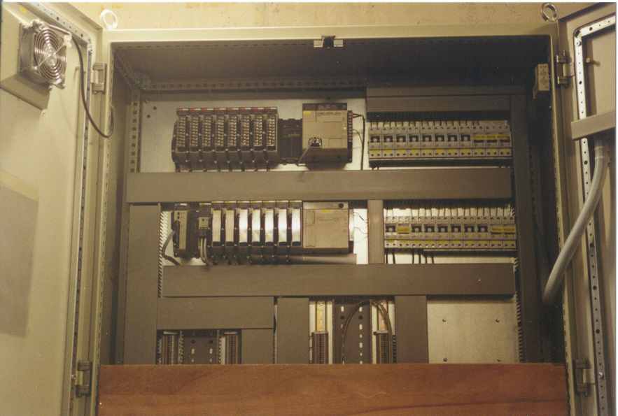
In order to drive the two hydraulic cylinders a strong electrical oil pump was installed. This pump provides the necessary oil pressure (c.200 bar). The oil pressure is transported via pipes to a second room. In this second room (cellar) are the electrically operated hydraulic valves. This valves control the speed of the pistons in the hydraulic cylinders that were connected to the large engine. The valves are operated by a computerized operating system (plc).
Via another set of pipelines the now precisely measured oil pressure arrives in the hydraulic cylinders in the engine room. This oil pressure of c.200 bar is sufficient to push the total overweight up (now c.40 t) in a reasonably short period of time. It is absolutely necessary that both hydraulic pistons move synchronously, if one piston moved faster than the other this could result in severe damage to the engine. Therefore a synchronizing cylinder is installed to control this process. Sensors continuously monitor the position of the hydraulic piston rods and feed this information to the computer.
The operation
At first the engine will be operated with two buttons, one for up and one for down. Later on the computer will be programmed in such a manner that the engine moves in the exact way as it did when steamed. This movement was rather irregular. The start of the up stroke was very fast, halfway up the engine slowed down and at the top of the stroke the engine stopped for brief moment, and then the engine started descending relatively slow. To simulate the fast up stroke a couple of extra provisions, that can supply high oil pressures in a short period, are necessary. These hydraulic accumulators store the energy that is produced by the descending 40 ton weight. The accumulators economically supply the extra energy for the up stroke, so the hydraulic oil pump does not have to all the work by itself.
The ideal future situation that the Steam Team has in mind is operating the engine with its original operating devices. This could be achieved by installing sensors on the original operating handles. But that still is a future dream.
The new technology