Introduction
The Cruquius engine has a peculiar and ingenious valve control system, the valve gear. Some time late in 2003 we as webmasters were approached with the question, would we know of someone capable of explaining this valve gear. Of course, we knew immediately who to contact. Jan Verbruggen was one of the few people who knew all the ins and outs. Jan did, of course, readily agree to try, but, he said: ‘Such an explanation is quite a task – I occasionally try to do it standing in the museum at the engine, really moving the handles, and even then only the more persevering of technophiles will stay with me till the end’.
As one can see, not an easy subject. But it is interesting to see how, at the time, the designers managed to ‘automate’ the control of the large and heavy valves of Cruquius. On this page we will tell you about the development of this valve control system. The following description will be mainly text, and is based on Jan Verbruggen’s notes. For a graphical presentation of the complex system of rods and handles, and the working of the valve gear, you can go to our special valve gear explanation page on the basis of several 3-D animations.
Three valves
At the time, it must have been quite a task and a challenge for engine-manufacturers to develop a valve control system for pumping engines (whether Newcomen, Watt or Cornish design). The Cornwall engine, of which Cruquius is an example, represents the pinnacle of this development. The valve gear is complex, because the engine has no rotative parts which could operate simple mechanisms like eccentric motion or cams. The valves must open and close at precisely the right moment, which requires accurate timing. In a Cornish engine the entire cycle is ‘automated’. Constant driver vigilance is required, but action is only required to start up the engine and to intervene manually.
For starters, for a brief survey of the valves and their function you can go to the animation on the demo page, for a more detailed description you can visit the steam cycle page.
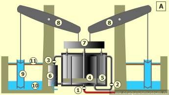
Three valves must be operated. (1) the steam or inlet valve, (2) the equilibrium valve, and (3) the exhaust valve. In the drawing above, these are indicated. At the start of the cycle the pistons are at rest at the bottom of their stroke, all valves are closed, and a vacuum exists in the condenser and under the annular piston. Now first, the exhaust valve is opened, which allows the spent steam from the previous cycle to be discharged to the condenser, where it is condensed by a jet of water, maintaining the vacuum. By opening the steam valve, fresh boiler steam is then admitted under the central piston. Steam pressure and vacuum together push this piston (and the linked annular piston) up, the pump pistons descend. About halfway up the steam valve is closed, the boiler steam now expands further. At the end of the stroke the exhaust valve is closed too. The engine comes to a stop in its top position. Next the equilibrium valve, in the bypass pipe between the spaces above and below the piston, is opened. This equalizes the steam pressure in those two spaces, the central piston is now in equilibrium, hence the name of the valve. The pistons and the crosshead (which is here also the weight) descend by gravity, assisted by the pressure differential across the annular or LP piston. The steam expands further. The pump pistons raise water. At the end of the pump stroke the equilibrium valve closes, and the engine comes to a stop in its starting position, ready for a new cycle to begin.
Development valve gear
The three valves of Cruquius engine are ‘double beat’ valves, i.e. they have two seats. The valves are operated by rods and levers, plus a weight. This weight would pull the valve open, if there were no further mechanisms to close it or keep it closed. From each valve a rod runs via an angular transformer to a lever on a horizontal arbor. This arbor also carries a handle. So we have three arbors, appropriately called the steam, equilibrium and exhaust arbors, each with a correspondingly named handle. The driver can use a handle to close a valve, but without further measures it would not remain closed. To effect that, each arbor carries a single pawl on a pawl wheel, which can be held in place (the valve’s closed position) by a lever engaging it. In Cornwall these are called the scoggan and scoggan lever. The three arbors run in bearings fitted to a frame at the central driver’s position. For a demonstration of the working of the valve you can go to the special double beat valve page.
What would happen if all three valves are open? The boiler steam could flow straight into the condenser. This must of course be prevented, usually by an arrangement which makes it impossible for the equilibrium and exhaust valves to be open at the same time. To this end, quarter-wheels or ‘quadrants’ are usually fitted to the equilibrium and exhaust arbors. If the equilibrium valve is open, its quadrant is turned into a position which is in the way of the exhaust-quadrant, and vice versa.
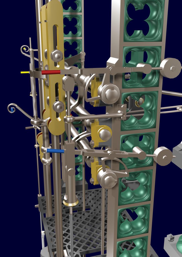
The steam valve (5) is operated via the steam arbor (1), the upper arbor in the valve gear frame. To control the valve there are three mechanisms:
a. To open: a weight (3). The valve opens itself by a weight that pulls the valve open.
b. To close: a rod (4) runs from the valve via an angular transformer (6) to a lever with a handle (2). An open valve is closed by the ‘plug rod’, which moves with the engine. The brass plug (8) on this rod can move the handle (2) of the lever on the steam arbor (1) and thus close the corresponding valve (5) (to allow a better view in the animation we left the rods out).
c. To remain closed: a pawl, the scoggan, which can be lifted by a short lever, the scoggan lever (7). This blockage ensures that the valve is not immediately pulled open by the weight when the plug releases the handle. The equilibrium and exhaust valves are controlled in a similar manner.
At the start of the cycle, both the exhaust and steam valves must open. Which of the two opens first, is of minor importance, but a big engine such as Cruquius works more smoothly if the exhaust opens first. Such large engines therefore often have a mechanism to ensure that the steam valve is blocked as long as the exhaust valve is not yet open. We now have a valve gear which enables the driver to manually open and close the valves.
To make the action fully automatic, we need two more additions: a closing mechanism and provisions for timing. A rod (or, in Cruquius, a double rod) is suspended from the beam, or from a lever linked to it. This ‘plug rod’ moves up and down with the engine piston. It carries projections (‘plugs’, but later usually called ‘slides’. These can engage with the handles to close the corresponding valves. If, for instance, the Cruquius’ steam valve is open and the piston is moving up, the plug rod moves down and the ‘steam slide’ closes the steam valve at a predetermined point in the stroke (e.g. at 50%, this is usually adjustable). In a similar way, the exhaust valve is closed at the end of the steam stroke, and the equilibrium valve at the end of the pump stroke. With this addition, all that is left for the driver to do, is to open each valve at the right moment by lifting its scoggan lever. In this way he normally starts up the engine. Once the condenser vacuum is built up and the engine runs smoothly, the remaining task of timing the valve action, can be left to the engine in various ways:
(a). Leave out the equilibrium and exhaust scoggans. At the end of the steam stroke, as the exhaust valve is closed, its quadrant will allow the equilibrium valve to open without delay. At the end of the pump stroke the opposite happens: the closing equilibrium valve releases the exhaust valve which, in turn, actuates a little rod opening the steam valve. As a result, the engine runs without pause at a maximum speed, determined by the steam supply. This system is used in the preserved canal pumping engines at Crofton in England.
(b). Leave out only the equilibrium scoggan. The exhaust (and subsequently the steam) valves will now not be released, the engine stops. For starting the next cycle, an additional mechanism is needed: the ‘cataract’ (nothing to do with eye disease, and only very little with waterfalls). This is how most Cornish engines are equipped. If you are interested in the working of the cataracts you can go to the special cataract page.
(c). For some Cornish engines (including Cruquius) a second adjustable pause was desirable, between the end of the steam stroke and the start of the pump stroke. In Cruquius this was needed to give the large pump clacks time to close. Such a delay is easily provided: fit a scoggan to the equilibrium arbor and actuate the scoggan lever with a second cataract.